
“Lost time is never found again.” – Benjamin Franklin.
The above quote is true to its core in context of distributed systems. If you miss out on keeping track of events in a cluster of 100+ machines then good luck building a system that acts as a source of truth.
Time is an essential component when dealing with events in an application. Time is used to answer questions such as:
- When did this event occurred?
- Out of these two events, which one occurred first?
- Out of these
nevents, which event occurred last? - What events occurred simultaneously?
In case of a single node application, the above questions can easily be answered by referencing the system clock. Whenever an event occurs you can record the current time and use this recorded time to compare with events that will occur in future to build a timeline. You can easily answer the above questions by comparing the recorded time and be sure that you have the right answer as there is only one source of time i.e. your system clock.
But this guarantee is no longer there once you move to a multi-node system. Due to clock skew, we can no longer be sure that system clocks on two different nodes yield the same time. Each clock can run at different rates and we can no longer reference system clock time for comparing the ordering of events occurring on two systems. So if Server_A writes Z=1 at time T1 and Server_B writes Z=2 at time T2, then we cannot ensure that Server_A wrote before Server_B even though T1 < T2.This turns out to be a major problem when dealing with events occurring in distributed systems with network partitions. You need a mechanism to find the correct ordering of events in order to ensure that system eventually reconciles to an agreeable state.
Vector clock is a data structure that achieves the goal of determining the causality of events occurring on different servers. The vector clock maintains versions of events on each server in form of an array. Considering we have a system of 3 nodes, we will have an integer array of size 3 where each entry is initialized to zero i.e. {0,0,0}. This array is tied to every event(For example set key Z=1 is an event) occurring on each node.
Let’s dive into an example to under stand how vector clock is used to determine if two events are concurrent or an event follows another event.
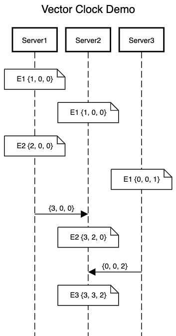
In the above example, we have three servers generating events. Initially all the three servers start with a vector clock initialized to {0, 0, 0}. Let’s start looking into how each event is handled on the individual servers:
- Event
E1is generated onServer1.Server1records the event by incrementing the vector clock by one the index mapping toServer1i.e. first index. This results inServer1vector clock to become{1, 0, 0} - Event
E1is generated onServer2.Server2increments its vector clock similar toServer1on its index making the vector clock ofServer2 {0, 1, 0}. - Event
E2is generated onServer1.Server1till now doesn’t have any information of events occurring on other servers. It moves forward by incrementing its vector clock to{2, 0, 0} - Event
E1is generated onServer3and it updates the vector clock in a similar manner to{0, 0, 1}. - Now
Server1sends an event toServer2. It sends an updated vector clock i.e.{3, 0, 0}as part of the request.Server2acknowledges that this event is not generated on its server but rather an event coming fromServer1. It needs to now perform a clock synchronization which is done by picking the maximum value for each servers. SoServer2first increments its own index to record the event and then synchronizes the vector clock making it{3, 2, 0}for eventE2. Server3similar toServer1sends an event toServer2with updated clock i.e.{0, 0, 2}.Server2performs another clock synchronization making clock for eventE3onServer2as{3, 3, 2}.
Above process is followed to synchronize clocks on servers. Once we have this synchronization in place, we can reference the vector clock of events occurring on each of these servers to find the causality of events. Rules to figure out ordering of two events based on their vector clock(V1& V2) is as follows:
- If majority of elements in
V1are less than or equal toV2and at least one element ofV1is less than element ofV2then we can say thatV1is causal toV2i.e. event associated withV1occurs before event associated withV2.- More formally it can be expressed as
V1 <= V2along withV1[i] < V2[j]fori = 1 to n.
- Finding this happens before relationship makes reconciliation of events easier in the system. If user sets
A=1onServer1as eventE1and setsA=2onServer2as eventE2then we can compare the vector clocks of these two events to figure out the ordering of events.
- Consider a simple case of event
E1occurring onServer1withV1as{1, 0, 0}and eventE2occurring onServer1withV2as{2, 0, 0}. Here majority(2 out of 3) of elements inV1is less than or equal to elements ofV2. So we can say thatV1is causal toV2. - For a more complex case, consider event
E2onServer1withV1as{2, 0, 0}and eventE2onServer2withV2as{3, 2, 0}. ComparingV1&V2we can figure out thatV1occurs beforeV2.
- More formally it can be expressed as
- If we cannot reach a conclusion from above comparison then we can say that two events are concurrent.
- If neither
(V1 <= V2 & NOT(V2 <= V1))nor(V2 <= V1 & NOT(V1 <= V2)) - In this case a common approach for reconciliation is to save both the events and shift the responsibility of reconciliation to client.
- Consider event
E1 onServer2with vector clockV1 {1, 0, 0}& eventE1onServer3with vector clockV2 {0, 0, 1}. Here neitherV1has all elements less than or equal toV2norV2has all elements less than or equal toV1.
- If neither
One of the famous real-life use case of vector clock is how DynamoDb uses it to maintain ordering of events. Dynamo is built to tolerate network partitions and it continues accepting writes even in case the nodes are unable to communicate across the partitions. This can lead to an object ending up in different states across two nodes. So for reconciliation, it uses vector clock of events associated with these objects to reach a final state.

References:
Server 2 E1 should be {0,1,0} instead of {1,0,0}?
Correct. My bad on the incorrect clock representation in diagram. For server 2 it should be {0, 1, 0} as the increment should happen on index corresponding to Server2 i.e. index 1 in the array.